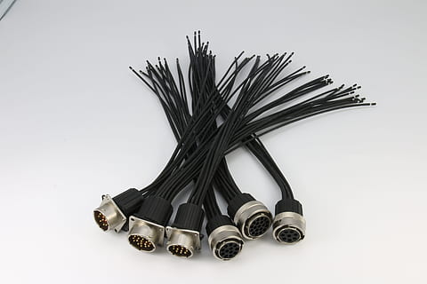
Death, Rs485 Cable And Taxes: Tips To Avoiding Rs485 Cable
페이지 정보
작성자 Dena 작성일24-06-03 08:10 조회21회 댓글0건관련링크
본문
These distances I'm talking about are greater than 100 meters. The WattNode® BACnet and Modbus® meters communicate using RS-485 (TIA/EIA-485-A) half-duplex, differential signaling at 9600, 19200, 38400, and 76,800 baud. The Serial 1 and Serial2 ports can be configured for either RS-232 or RS-485 communications at standard baud rates up to 115200 bits per second. Although the maximum standard baud rate of the primary serial port is 19200 baud, nonstandard baud rates of over 80 Kbaud can be attained by the 68HC11's on-chip UART and the onboard RS232 driver. A jumper, J3, configures the primary serial port for either RS232 or RS485 operation. All of the serial ports are supported by pre-coded C-language software drivers that make it easy to exchange data. Typical line voltage levels from the line drivers are a minimum of ±1.5 V to a maximum of about ±6 V. Receiver input sensitivity is ±200 mV. If you are using the QScreen as a slave device and require the /SS signal for your external SPI hardware, configure one of the Port A pins on the Field Header as an input pin. Henceforth, we shall consider Slave devices to be measuring instruments with serial communication, even if the cabling is similar for all Modbus devices.

The SCK (serial clock) pin is a configurable synchronous data clock output. Thus, the master has only one input, MISO, which is the slave’s only output. For the transfer of data, the baud rates of both Master and Slave must be between 10% of each other. A Modbus RS485 connects a Master device to one or more Slave devices. The GROUND line serves as a common voltage reference for the master and slave. Slave devices use the master in/slave out pin, MISO, for transmitting, and the master out/slave in pin, MOSI, for receiving data. Setting the MSTR bit initializes the QScreen as a master, and clearing the MSTR bit initializes it as a slave. The SPIE bit in the SPCR (SPI control register) enables SPI interrupt handling. But if you are building a control system with these development boards over a distance greater than 10 to 15 meters, then you should take the noise and signal power into consideration because if you want your system to work reliably, then you cannot afford to lose the data while transferring.
5V power supply and the rated current is 300 μA. The cabling of the industrial communication systems (Modbus RS485) is different in some ways from the cabling used for power cabling and the electrician may experience some difficulties if he is not an expert in Modbus communication networks. All communication cabling to be installed in a daisy chain configuration, no T’s are permitted. Because they are produced in such large quantities, Cat 5 cables are relatively inexpensive, often less than half the price of specialty RS-485 cabling. The capacitance is close to 12.5 pF/foot but there is a small impedance mismatch (100 ohms for Cat 5, 120 ohms for RS-485). We have been using Microcontroller Development Boards like Arduino, Raspberry Pi, NodeMCU, ESP8266, MSP430, etc. for a long time now in our small projects where most of the times distance between the sensors and board is not more than few centimeters at max and at these distances, the communication between the different sensor modules, relays, actuators, and controllers can be easily done over simple jumper wires without us being worried about the signal distortion in the medium and the Electrical noises creeping into it.
Previously we have also performed MAX485 communication with Arduino and also MAX485 Communication with Raspberry pi, you can also check them out if interested. Most of the low-cost sensors and other modules like GPS, Bluetooth, RFID, ESP8266, etc. which are commonly used with Arduino, Raspberry Pi in the market uses UART TTL based communication because it only requires 2 wires TX(Transmitter) and RX (Receiver). Since it uses a differential line over twisted pair (like EIA-422), it can span relatively large distances (up to 4000 feet or just over 1200 metres). There are many different types of serial communication protocols like I2C and SPI which can be easily implemented with Arduino and today we are going to look at another most commonly used protocol called RS485 which is very commonly used in high noise industrial environments to transfer the data over a long distance. In this tutorial, we are going to learn about the RS485 communication protocol and how to implement it with the two Arduino Nano we have with us and how to use the MAX485 RS485 to UART conversion Module. But You stated you are going to install this at a commercial setting, so it always better to use the worst case environment situations, and use shielded cable.
If you have any issues pertaining to exactly where and how to use rs485 cable, you can call us at our own internet site.
댓글목록
등록된 댓글이 없습니다.
